The phase-locked loop (PLL) is one of the least-understood of all major analog electronic circuits. It is frequently explained badly, or only half-explained in a way that does not effectively communicate how it works or what it is meant to do. This page endeavors to begin by explaining the simplest possible PLL first, then explaining exactly what the device is meant to accomplish.
Before we even discuss the very simplest PLL, however, we need to first understand the two key components that go into a PLL: The phase detector and the voltage-controlled oscillator (VCO).
A phase detector has two inputs and one output; the two inputs receive electronic signals, which the phase detector compares the phase relationship between. The phase detector outputs a voltage based on the phase relationship between these two signals.
The classic example of a simple, intuitive phase detector is a 2-input XOR gate. Recall from digital logic that such a gate will output a 0 if both of its inputs are the same (i.e. both 1 or both 0), but it will output a 1 if the inputs are different. Therefore, an XOR acts as a sort of "out-of-phase alarm", creating a high voltage whenever its inputs are out of phase, but staying dormant as long as both of the inputs are perfectly in sync.
More complex phase detectors (which are pretty much required for proper phase-locked loops) do not have simple binary outputs; rather, they have analog outputs which vary linearly based on how out-of-phase the input signals are. If the signals are perfectly in phase, the output of the phase detector is typically zero. If the first signal starts creeping ahead of the second, the phase detector's output may rise accordingly, and if the first signal starts falling behind the second one, the phase detector's output may go low. (I say "may" simply because this description is arbitrary, based on which input you think is the "first".)
The VCO is just that: An oscillator with an input line that will vary the speed of oscillation. Typically, a higher voltage going into the VCO will make it speed up, while a lower voltage will make it slow down. VCOs generally also have a fundamental frequency they run at when the input voltage is zero; this may be known as the fundamental frequency, the center frequency, the free-running frequency, or the quiescent frequency. These terms mean the same thing; they're just a matter of terminology.
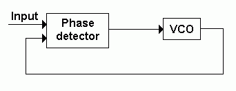
Fundamentally, the PLL is nothing more than a phase detector and a VCO, wired in such a way that the phase detector's output forms the input to the VCO, and the output from the VCO forms one of the inputs to the phase detector. The "loop" part arises because these two devices feed into each other, causing them to enter a mutual relationship in which each affects the operation of the other. The result looks like this when rendered as a block diagram:

A signal is sent into the PLL from some signal source, like a function generator. The two parts of the PLL will then try to work with each other so that the output of the VCO is identical to the input to the phase detector: If the VCO starts lagging behind the input, the phase detector will note this and speed up the VCO slightly to keep the two signals aligned, and if the VCO gets ahead of the input signal, the phase detector will make the VCO slow down just a bit. (This method of using a loop to auto-compensate for errors in output is what's commonly called "negative feedback".) The result is a VCO output that mirrors the input signal. That's your basic PLL.
Now, if you've read and understood everything to this point, you might be thinking: Okay, that's great, so the PLL is a system that automatically tries to make its oscillator mimic the input, but what's the point? All you've done is create an exact duplicate of the input! If you wanted that, you could have just used the input to begin with! Isn't that completely useless? The answer is: Yes, you're right, the VCO output of the PLL that's just been described is indeed useless on its own, but the possibilities open up when you start adding extra components to the mix.
Before we add anything else to this PLL, however, it's worth mentioning that the ultra-simple PLL described above can indeed fulfill one of the most important applications of a PLL. Unlike most other PLL applications, however, this one uses not the output of the VCO, but rather the output of the phase detector. Remember, the output of the phase detector is a simple voltage which changes based on frequency shifts of the input signal. Mathematically, it is the instantaneous change in the input frequency. The signal which comes out of the phase detector is usually called the "error signal", because it typically represents any failure of the two signals to remain in sync with each other, but if the input signal happens to be an FM radio signal, then the output of the phase detector is no error; it is the very audio stream that the FM transmission encodes. Therefore, a basic PLL can be used as an FM demodulator.
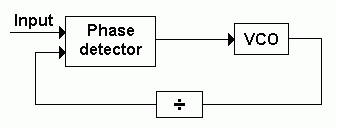
From this important application, let's move on by adding more blocks to our PLL. Possibly the simplest example of something practical you can make with a PLL by adding extra stages is a frequency multiplier. Suppose that instead of connecting the VCO's output directly back to the phase detector, you insert a frequency divider into the link. A frequency divider is simply a device which "swallows" input pulses at a regular interval; for example, a device that alternately passes and ignores pulses is a divide-by-two circuit, because it only outputs half as many pulses as it receives. Imagine you had a PLL like the one illustrated above and ran it for a while, then suddenly plugged a divide-by-two frequency divider, like this:

What's going to happen? Well, the phase detector, which just a moment ago thought its two inputs were nicely in phase with each other, is going to think "Uh oh, the VCO is lagging way behind my other input. I'd better speed it up." It will then do exactly this, until the two inputs seem to be back in sync with one another. But what's actually happened is that the VCO is now running at twice the speed of the input; it's just that half of the VCO's output is not being seen by the phase detector. We have effectively made a frequency doubler. You can make a frequency tripler by using a divide-by-three divider, a quadrupler with a divide-by-four, and so on.
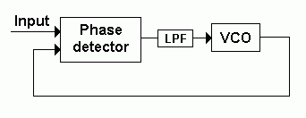
Another excellent application for PLLs is signal cleanup. Suppose you have a noisy signal, afflicted with occasional glitches that might wreak havoc on a digital circuit if you're using that signal as a timing clock. You can make the PLL smooth this noisy clock out if you add a low-pass filter (LPF) between the phase detector's output and the VCO's input, like this:

The low-pass filter is simply a device that resists sudden changes in voltage; if a steady voltage change is applied to it, the LPF will slowly come around and start moving to the new voltage, but sudden spikes in voltage just get absorbed. With the LPF inserted into the PLL, the phase detector cannot make rapid changes to the VCO's input. If it really needs to make a permanent change, it will gradually be able to do so as the LPF allows the voltage to slide over, but sharp, sudden spikes caused by glitches in the input signal are mostly absorbed, resulting in a relatively stable signal coming out of the VCO, which can then be used in place of the noisy signal.
When a device reads a digital data stream, it needs an input clock to know where to read each bit from the stream. This is easy enough if there are two separate data lines--one for the actual data, one for the clock to time that data--but there are several types of data stream which are sent with no clock information, including many types of telecommunications transmissions, as well as the data that comes from a disk drive's read head. When you have a signal like this, you must synthesize or "recover" the clock for that signal. This can be a bit iffy, because it's basically making an educated guess as to how fast the clock is and where its transitions are, but clock recovery is a long-standing practice with a variety of standard circuits in place to achieve this job.
Many clock recovery circuits simply use a PLL for clock recovery, configuring the center frequency of the PLL's VCO to the actual frequency of the data stream, then using the data stream as the external input to the phase detector. This obviously means that the two inputs to the phase detector will be out-of-phase whenever the data stream stays high or low instead of transitioning (since it will not necessarily change after every single clock cycle), but the low-pass filter on the PLL will smooth out these variations so that the VCO's output stays reasonably constant. To aid in this process, a bit-encoding standard is usually used that minimizes gaps in which the data stream fails to transition; for example, common computer disk bit encodings are rigged such that no more than 2 consecutive magnetic bits may have the same polarity, ensuring that the data stream will only go for a maximum of 2 bit times without a transition.