Quartz is silicon dioxide, which has a chemical formula of SiO2. It is the world's most common mineral; It's the main component of common sand.
Although quartz is not conductive (meaning it doesn't carry electricity like most metals such as copper), it has certain electrical properties that make it very useful for certain electronics. In particular, it is piezoelectric. "Piezoelectricity" is a word derived from the Greek word "piez" or "piezein", meaning "to press"; Piezoelectric materials are non-conductive materials which generate electricity when you subject them to pressure, and vice-versa: They undergo physical deformation when you run electricity through them. If you compressed a pice of quartz using a pair of pliers or a vise, it would generate a very small electrical charge, and if you connected a piece of quartz to either end of a battery, the crystal would bend or warp slightly. These effects are too small to be visible to the human eye; You won't actually see the crystal bending or shaking, and you won't notice sparks coming from it, but there will be very tiny effects, and these can be detected and used by electronic circuits.
The precision of quartz crystals makes them very valuable to modern electronics; However, quartz found in nature is not usually pure enough to be useful in a precise electronic circuit, so artificially-made quartz is usually used in today's manufacturing world. Once the quartz crystal is cut into a bar or disc shape, it has two electrical leads attached to it and the entire crystal is plated with some protective metal coating. The resulting metal-coated-crystal with two pins sticking out of it is the common crystal of the electronics world. The crystal is rated for a certain frequency, which is basically how quickly it vibrates when you electrify it; The frequency of a crystal is mainly affected by how thick it is, and so crystals of widely varying frequencies can be achieved just by cutting them to a certain thickness.
Once you have this production crystal, however, it does not generate a perfect, constant oscillation by itself, even after you run electricity through it; The crystal must, in an ironic twist, receive its own frequency to keep vibrating. This is because the crystal acts as a filter. (A filter is an electrical device that allows certain frequencies to pass, and blocks others.) So once you start the crystal vibrating with an initial jolt of electricity, the output of the crystal must actually be fed back into itself, creating a feedback loop that keeps the crystal vibrating. Thus the crystal's output must have at least two connections, one through a channel that feeds it back into the crystal, and another that amplifies the output for use in the actual application that required the frequency in the first place. (Unless the crystal is not being used for anything and you are just experimenting with it.)
All crystals can be operated in series-resonant or parallel-resonant mode. These two modes result in two frequencies from the crystal that are slightly different, but only slightly. Usually, a crystal is specified as being serial- or parallel-resonant, meaning it will operate at its rated frequency in that mode; However, you can run it in the other mode as well, you just will get a slightly different frequency.
During discussions of crystals, the terms "harmonic" and "overtone" often come up. A harmonic of a crystal is a whole-number multiple of its fundamental frequency. For example, if you had a 10 MHz crystal, then 20 MHz would be its second harmonic, 30 MHz its third harmonic, and so on. An overtone is an odd-numbered harmonic of the crystal. For example, in a 10 MHz crystal, 30 MHz is known as the crystal's "third overtone", and 50 MHz would be the "fifth overtone".
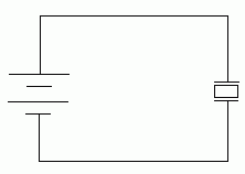
Those are the basics of crystals. The question, then, becomes: How do you actually create a circuit which oscillates with a crystal? As mentioned before, you can't simply connect the crystal to electricity and expect it to start oscillating. Such a circuit would look like this:

In a proper oscillator circuit, the quartz crystal must resonate, and in order for that to happen, the crystal's own vibrations must be fed back to it; These vibrations will shake the crystal yet again, and a constant vibration will be created that is the actual oscillation of the circuit. So how do you get the crystal to feed back into itself? You might first think you could do it with a circuit like this...

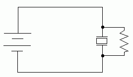
...Unfortunately, that will not work. For starters, it's a short-circuit across the power supply, and you're going to burn out the power supply (or blow the fuse in it) if you try using this circuit because the electricity can travel directly through the branch around the crystal. You might think that you can avert this problem by putting a resistor on the feedback loop. The result would then look like this:

That will also not work, because while the crystal will receive a tiny bit of its own vibrations, that little bit won't be enough to keep it going. If this circuit could work, the crystal would be acting as a perpetual motion machine. Have you seen the drawings of ideas for machines which never stop running, because they have a mechanism which outputs power back into themselves? If you've ever read about such machines, you know that they don't work, because they can't create more power than they use. It is a basic principle of science that energy cannot be created or eliminated; Energy only changes forms. A machine will always eventually stop running, because energy will keep getting wasted until finally it's all gone. In the same way, this circuit won't work because eventually the crystal's vibration will lose all its energy.
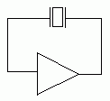
What the crystal needs is something that will actually increase the energy of its own vibrations. The device that will do that is an amplifier. An amplifier is, after all, simply a device that takes whatever goes into it, and outputs the same thing, only stronger. A crystal oscillator circuit, then, conceptually looks like this:

In this diagram, what you're looking at is an amplifier (the triangle at the bottom is the symbol for an amp) which is actually wired back into itself, so that whatever it outputs goes back into its input again. As you can imagine, every time the signal goes around the loop, it will get stronger and stronger, getting amplified each time it goes around, until the amp reaches its limit. This is called a feedback loop, because the amp's output is fed back into itself. Feedback is interesting in many ways; It's what creates that annoying whining sound that you sometimes hear when a microphone gets too close to a speaker it's connected to. As sounds come out of the speaker, they go back into the microphone, through an amplifier, and back out the speaker again, only louder. The result is a loop that keeps making louder and louder sounds, until soon the circuit is overwhelmed and a terrible noise is created.
As you'll notice, however, in this diagram, there is a quartz crystal placed in the feedback loop. Because the crystal is a filter, it will only allow its resonant frequency to pass through. The result is that the feedback loop will start to vibrate at the crystal's resonant frequency, and the crystal will block anything else that tries to get through. The feedback loop ends up being the oscillator output.
Of course, this diagram does not detail the complete circuit, but it's a good illustration of the central focus of a crystal oscillator. The main thing missing from the diagram are the power connections that actually power the amplifier; Amps aren't perpetual-motion machines either! They need electricity to run! Also, you'd assume that if you're going to all this trouble to make the circuit oscillate, you'd want to hook up something to it to receive those oscillations. This circuit will oscillate as is, but to actually see or use the oscillation, you'd need to connect something to the feedback loop (which, again, is the oscillator output). A great many diagrams which illustrate crystal oscillators will also detail the actual workings of the amplifier itself; The result is more of an amplifier schematic than an oscillator schematic, because they're basically just amplifiers built around a crystal. But the simplest crystal oscillator circuit schematic is still just a crystal wired in series with the input and output of an amplifier.
You might wonder how the whole thing gets started. After all, the crystal needs to RECEIVE some of its own frequency to start PRODUCING that frequency, right? The answer is yes, but the initial surge of electrical noise that hits the crystal when the power first comes on is enough; That jolt makes the crystal vibrate just a little bit, which is enough to get the feedback loop started.
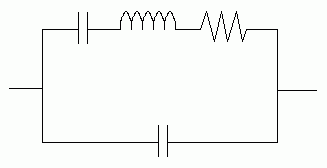
You may also hear about a crystal resonator's equivalent circuit, which is a circuit that behaves just like a quartz crystal would. This equivalent circuit is basically two parallel branches. In one branch, a capacitor, an inductor, and a resistor are wired in series. The capacitor and inductor form the resonant circuit (because capacitors and inductors create resonance when they're wired together this way), and the resistor is the inherent resistance of the crystal itself. The other branch of the crystal's equivalent circuit is a single capacitor, which actually represents the capacitance of the metal leads that attach to the crystal, which indeed form a capacitor themselves. The described equivalent circuit looks like this:

You could, in theory, create a circuit like this and have it behave just like a crystal. Crystals, however, are much more efficient, because they're way smaller than all the components in this equivalent circuit, and they're also much more precise.
All of this has applied to the cheap two-pin crystal devices that are quite commonly found in electronics. To simplify the details of using quartz oscillation, however, a somewhat more elegant and expensive type of device has been created: The fully-contained quartz oscillator. These are devices which are noticeably larger than simple crystals, and instead of two pins, they have four pins. However, their pinout is extremely simple. It looks like this:
+V /ÄÄÄÄÄÄÄÄÄÄÄÄÄÄÄÄÄÄÄÄÄ\ Output
ł14 8ł
ł ł
ł ł
ł ł
ł1 7ł
NC ŔÄÄÄÄÄÄÄÄÄÄÄÄÄÄÄÄÄÄÄÄÄ/ Ground
(Who says ASCII art is dead?)
Although three of the oscillator's four corners are rounded, one is sharp and right-angled instead; That is the oscillator's pin 1, and it is not connected to anything. All the other three pins are, however. The other pins are numbered 7, 8, and 14, because even though there are only four pins (so the second pin is "pin 7"), they are spaced so far apart that pin 7 has room for five other pins between itself and pin 1. This numbering is done to keep things orderly so you can match up pin numbers with ICs on your circuit board. Pin 14 is the voltage input (usually these oscillators are made to receive +5 volts input), and pin 7 is the ground pin. Pin 8 is the output, and as soon as the oscillator is powered up by connecting pins 7 and 14, the oscillator has been turned on, and it is outputting a nice oscillating wave on pin 8, at whatever frequency the oscillator is rated for. Simple, wasn't it?